
Eliminating Waste in Industry
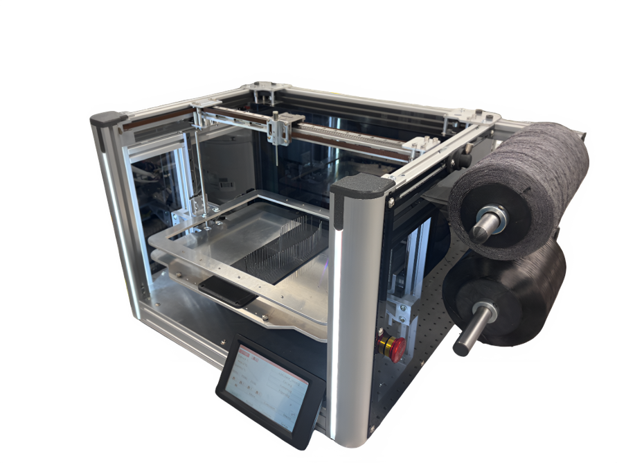
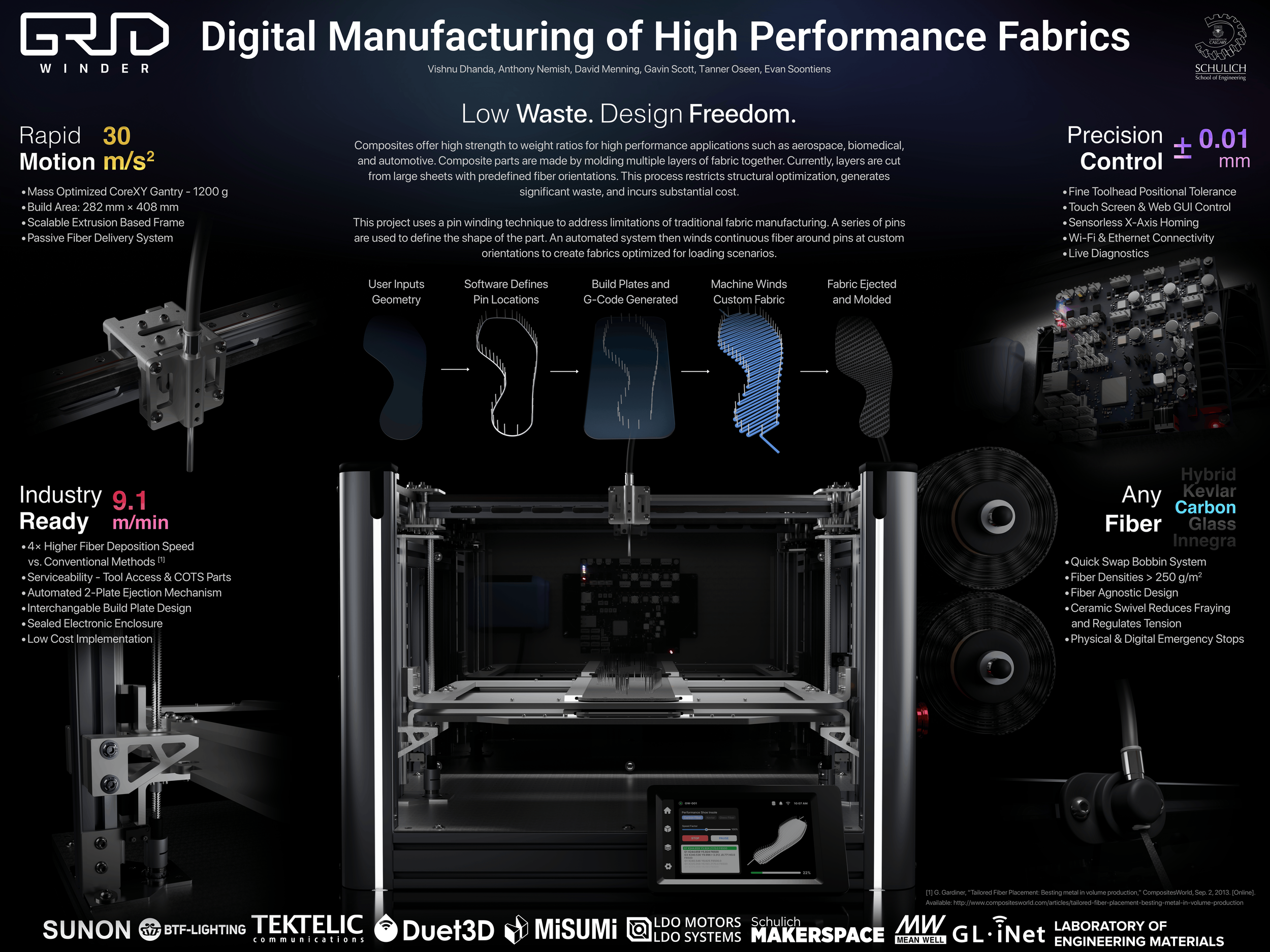
At the moment in industry, acquiring precise, repeatable custom shapes for composites like carbon fiber, fiberglass, or Kevlar is done using CNC cutting on a large sheet. This method is useful for simple shapes that easily pack together on a sheet, though when intricate shapes are needed, waste can be high. The GridWinder serves as an option for industries looking to eliminate waste using it’s new and novel winding technique as seen above. This technique also allows for custom fiber angles to be used, giving companies much more control over the mechanics of final parts compared to current industry methods. This is due to the anisotropic nature of carbon fiber, in which an engineer can design parts with angles specific to the directions of loading.
Democratizing Custom Composite Parts
Currently, if a small-scale company or startup desires to create their own repeatable composite parts, they would need to outsource that production. This increases cost and reduces their already thin margins due to wasted material. The GridWinder is a scalable, affordable machine that runs on the common voltage found in homes and regular buildings, which can get any company up-and-running without the need for massive machines or retrofitted electrical systems.
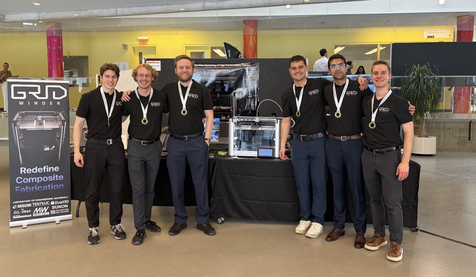
On April 1st, 2026, the GridWinder team attended the annual engineering design capstone fair at the University of Calgary, in which we took home gold in the multidisciplinary category. This category is known for having the best projects the school has to offer due to the large range of skills that multiple disciplines can bring to one team.
This was one of, if not the most valuable day of my engineering career. I got the opportunity to speak to so many people about the project and get them excited about the technology.
My Role on the Team
During the preliminary design phase of this project, I was responsible for planning out and executing the entire post processing stage and creating the accompanying molds, as well as designing the peripherals of the system. After the machine was designed in CAD by everyone and consolidated, it became a team effort to manufacture the parts, assemble the machine, and troubleshoot problems as they came up during testing. Below is a rundown of the post processing stage in which the fabrics that are ejected from the machine can be turned into final useful parts, as well as all of the peripherals that I designed and created.
Post Processing Stage
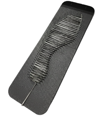
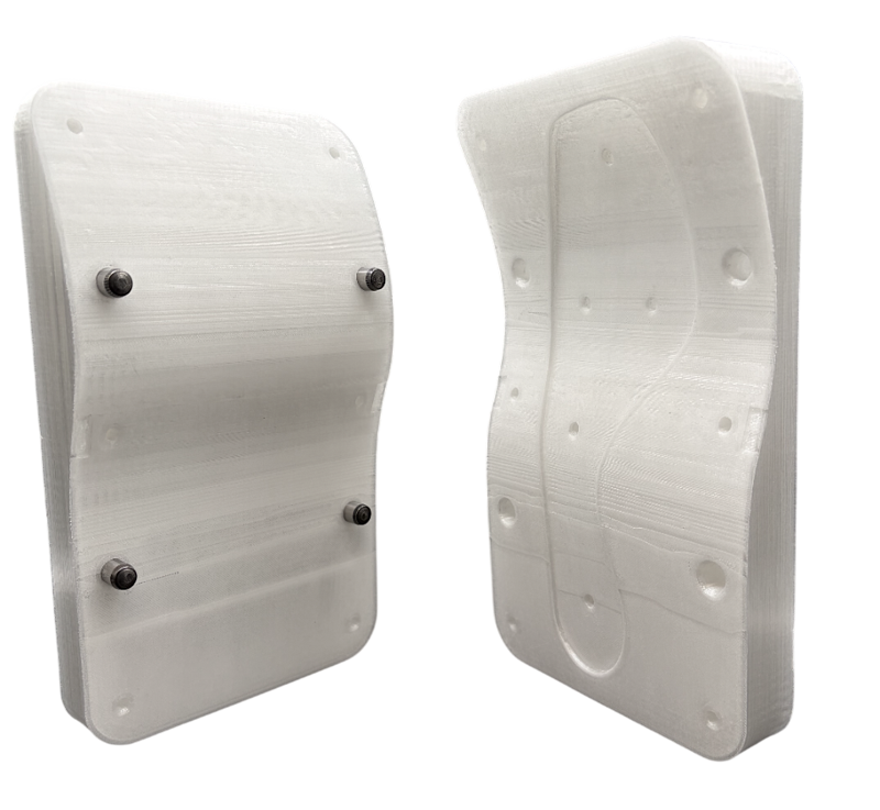
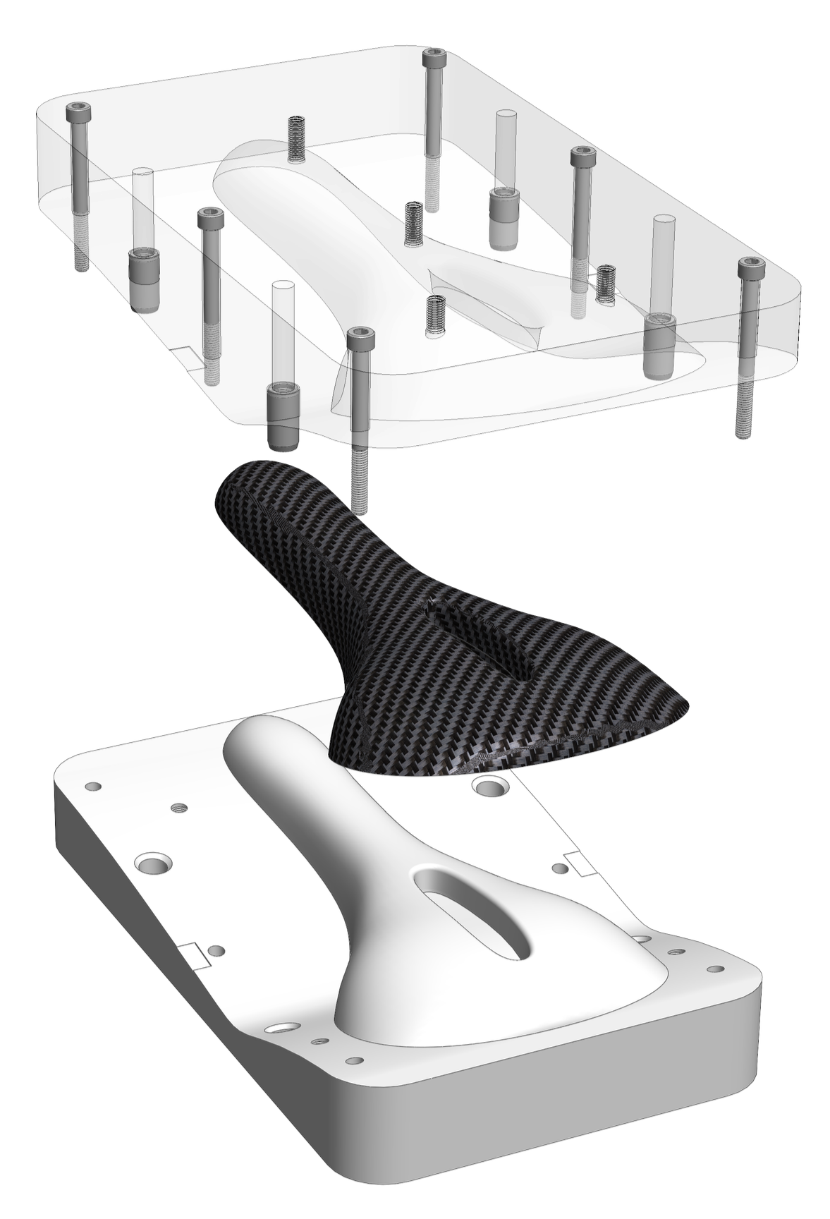
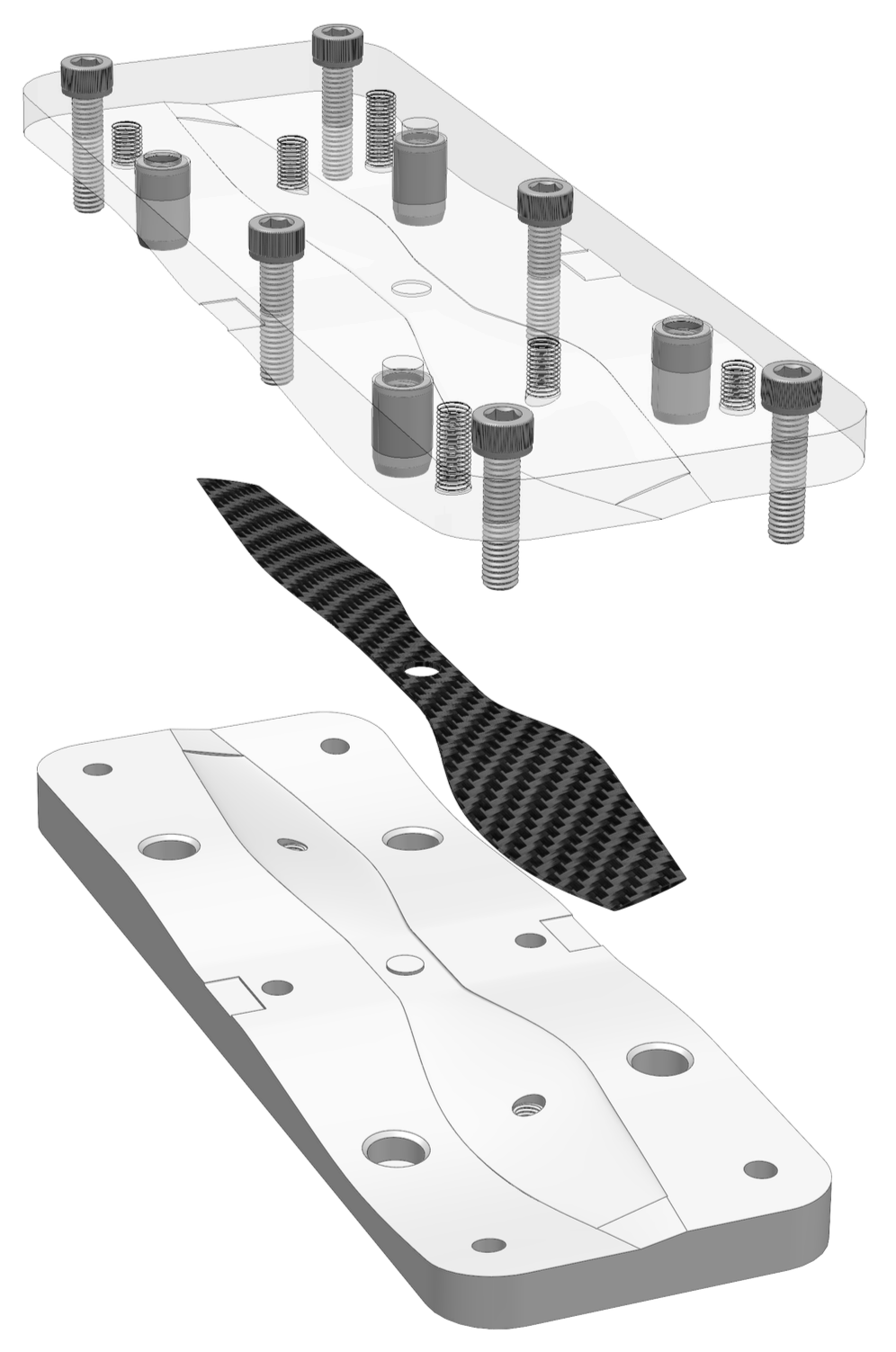
After the machine winds the fiber around the pins and ejects the fabric, it is ready for the molding process. This is done using a two-part 3D printed mold and epoxy resin. The mold has a layer of release wax applied to both sides of it, and then the epoxy resin, followed by a layer of the wound fabric, more epoxy, another wound fabric, and so on until the desired thickness of the part is reached. The mold is then clamped together and the resin is given time to cure.
The mold is designed with the following features that have been used to give us high quality parts:
Holes for alignment dowels that are used to perfectly line the two halves up.
Clearance holes around the outside which are used by nuts, bolts, and washers to give proper compression while curing.
Thin slots on the sides to allow for a flat-head screw driver to be inserted and pry the two halves apart.
Threaded features on the cavity section in which long bolts can be inserted and apply slow, even pressure to the part for a successful release.
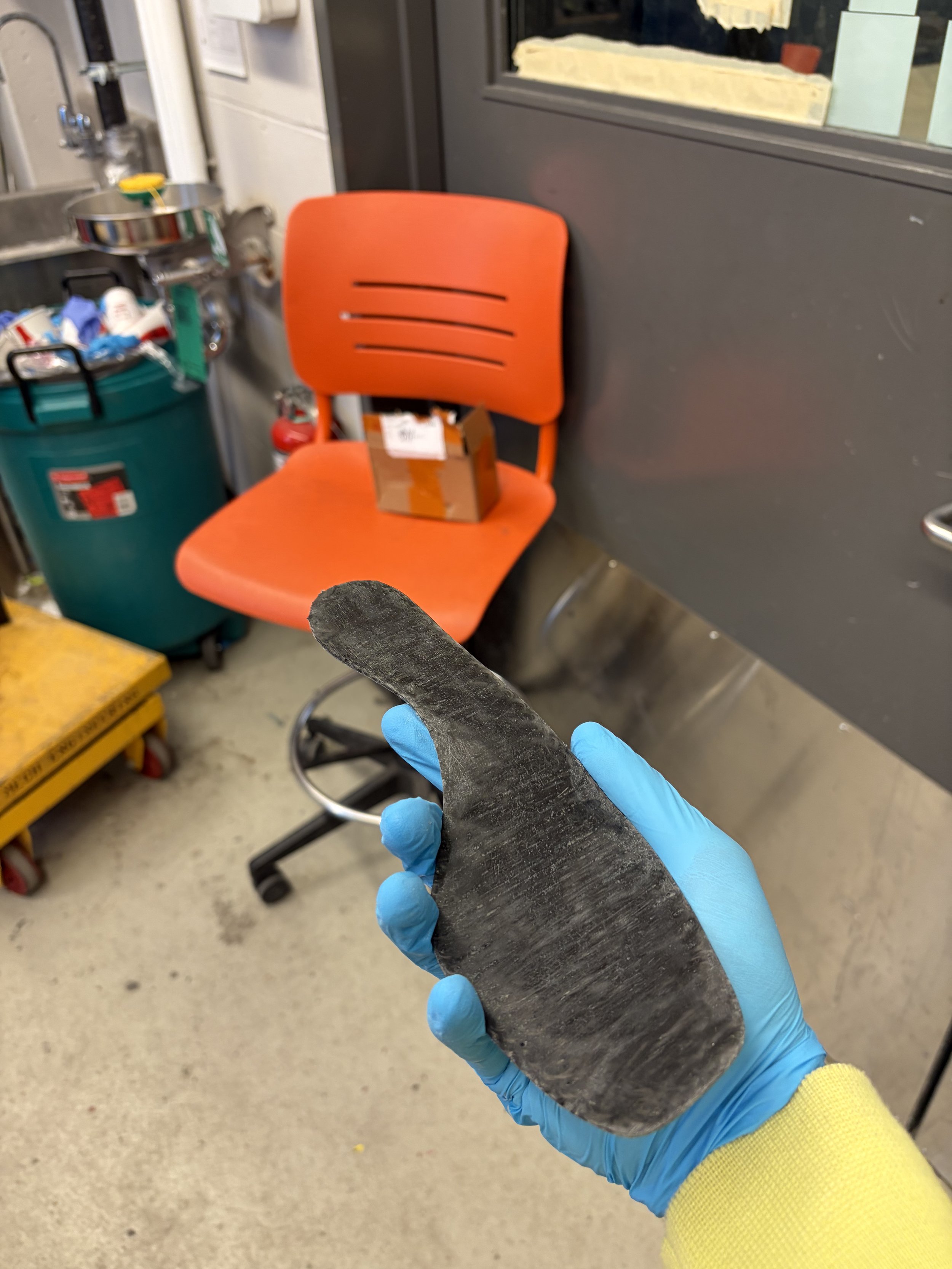
The three parts shown below are of a shoe midsole, bike seat, and drone propeller. Carbon fiber shoe midsoles are used in industry to give high performance running shoes extra stiffness, allowing for higher energy returns and therefore a faster shoe. Composite bike seats and propellers are commonly found on high performance race bikes and drones, as they provide an ideal ratio of strength to weight. We are investigating more use cases for this machine in the aerospace, automotive, and biomedical industries, and are specifically targeting shapes that are either already flat or easily drapable, as seen in these three examples.
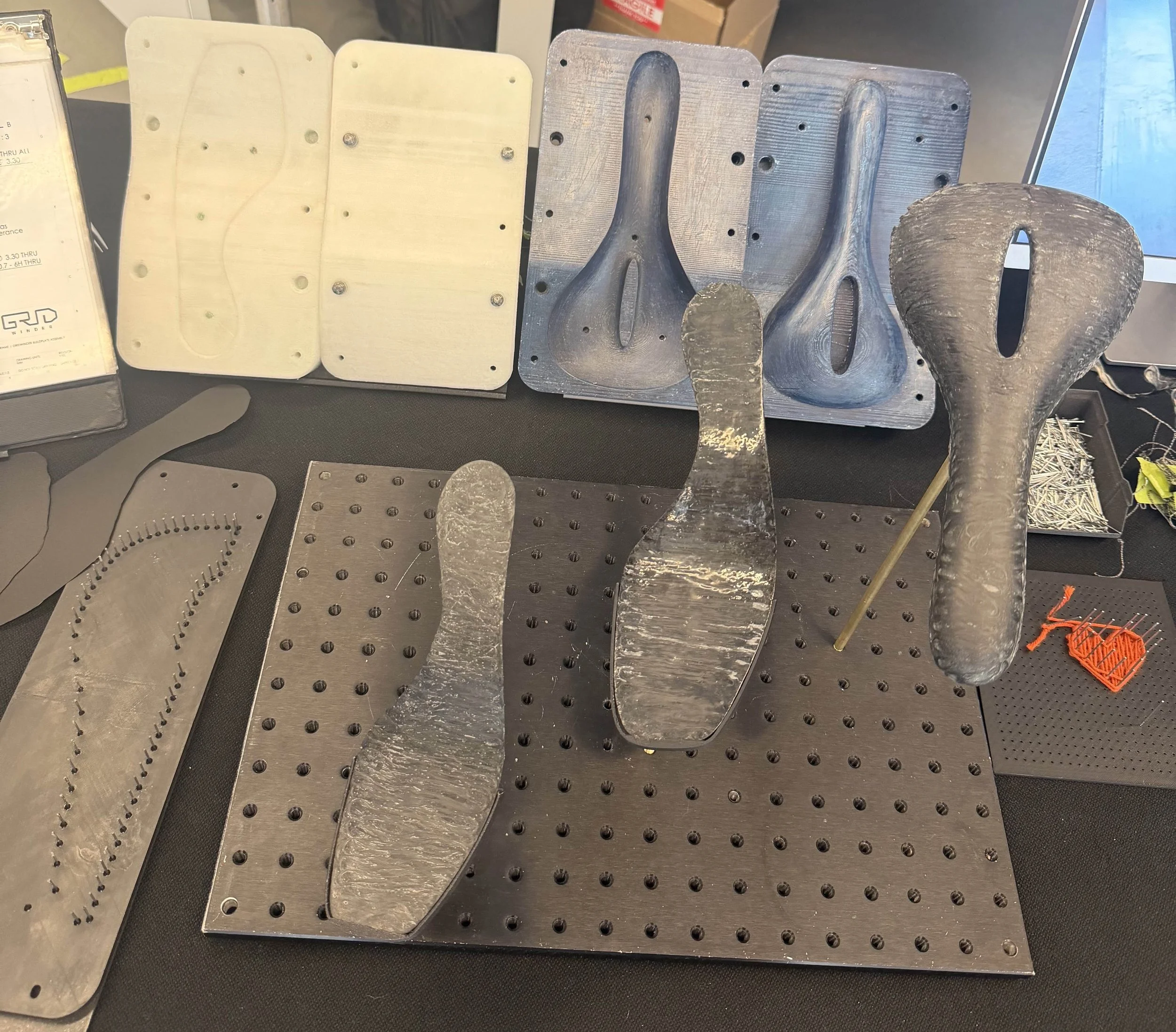
Layout of demonstration parts at the engineering design capstone fair
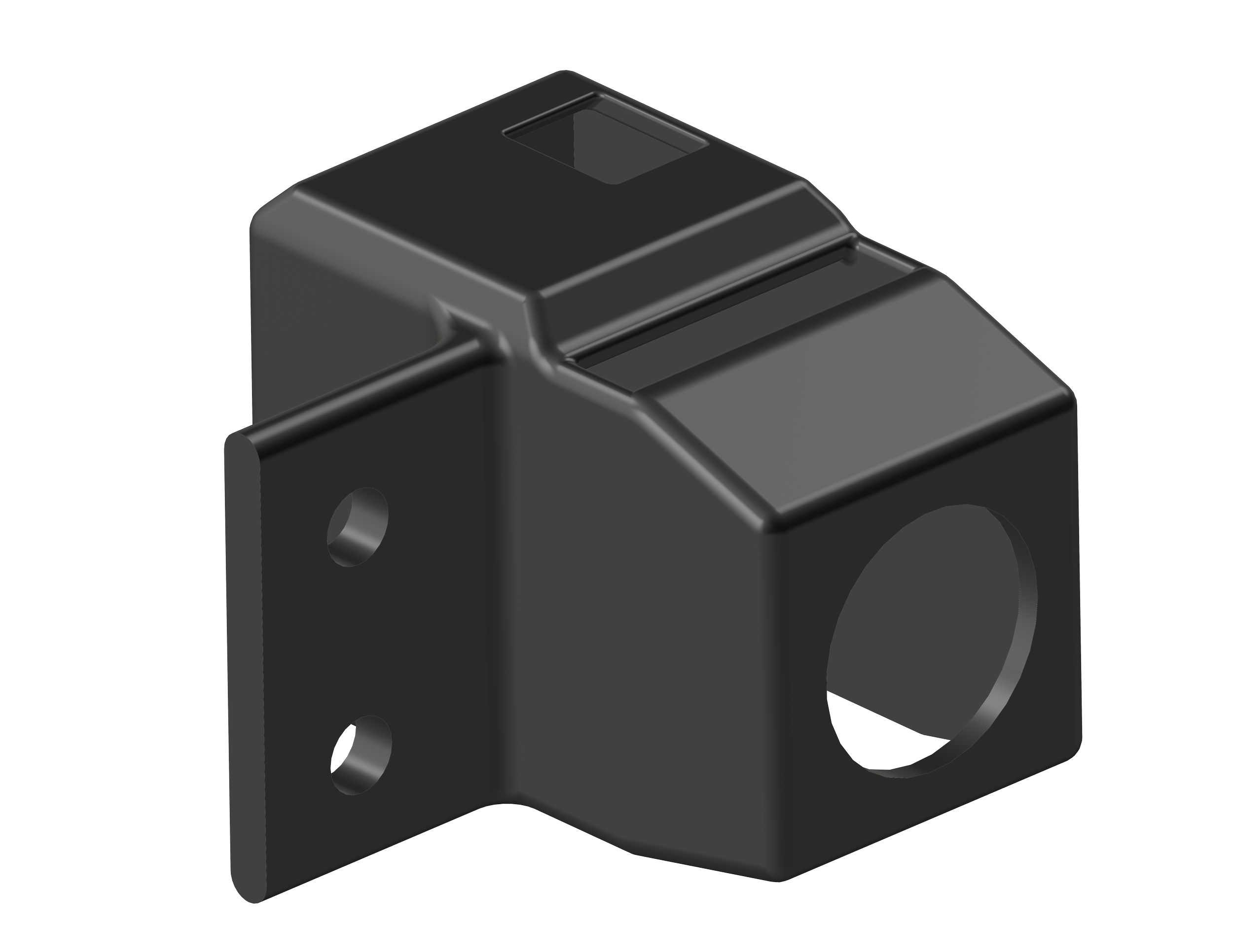
Emergency Stop Mount
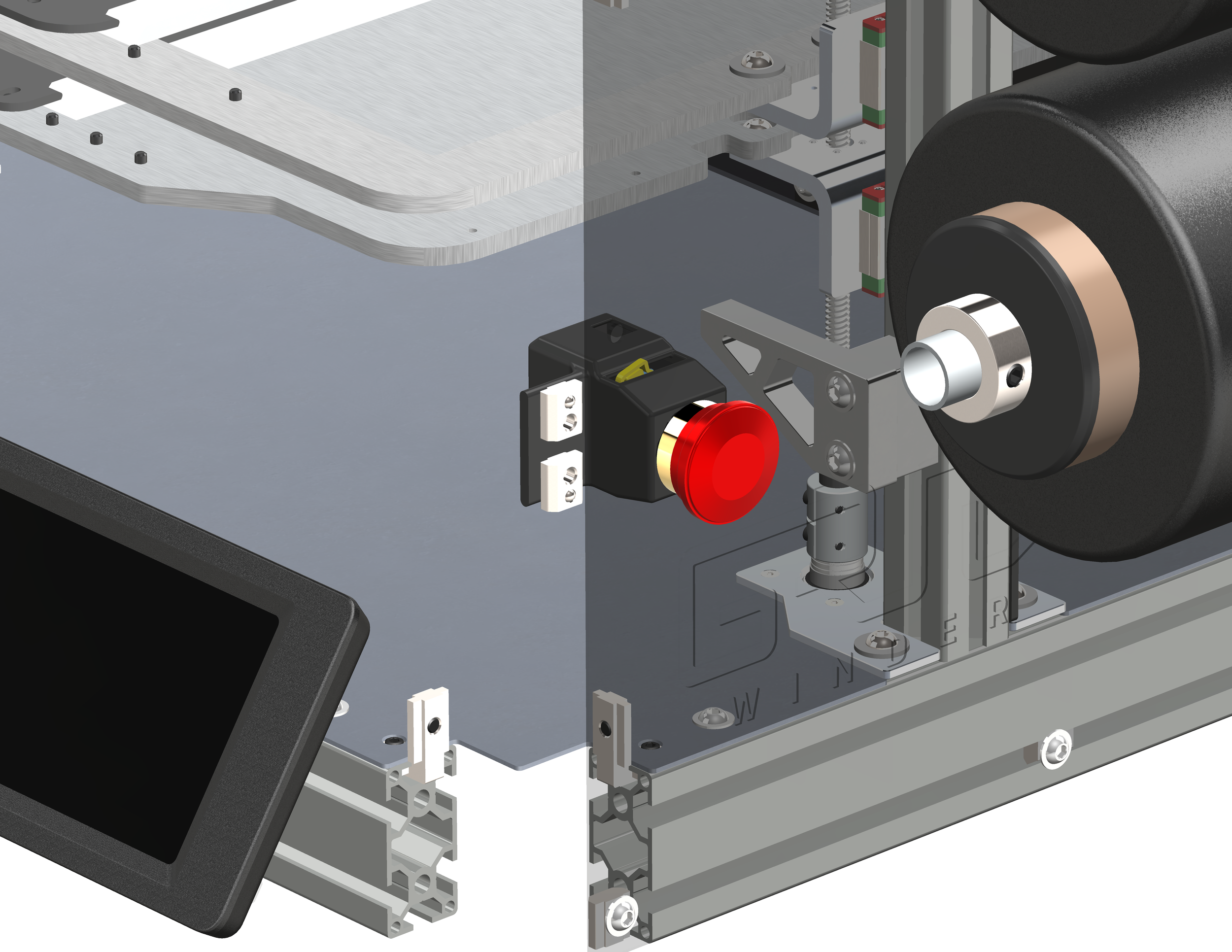
The emergency stop is a critical safety component of the machine, and as such needed a sturdy mount that could withstand the forces it of it being struck in case a problem arose. The mount also needed to be able to hide the electronics of the button and the wire leading out of it. Due to this need a total enclosure was required, as well as a channel for the wire to travel through on the back.
This part went through four major redesigns over the course of the design phase, as different needs were addressed and shortcomings discovered when using the early versions of the mount. The design started as a much taller mount, having the wires leading out of the top of the button and routing inside the mount, though this was considered undesirable by the team and so this shorter, more streamlined and angular mount was created.
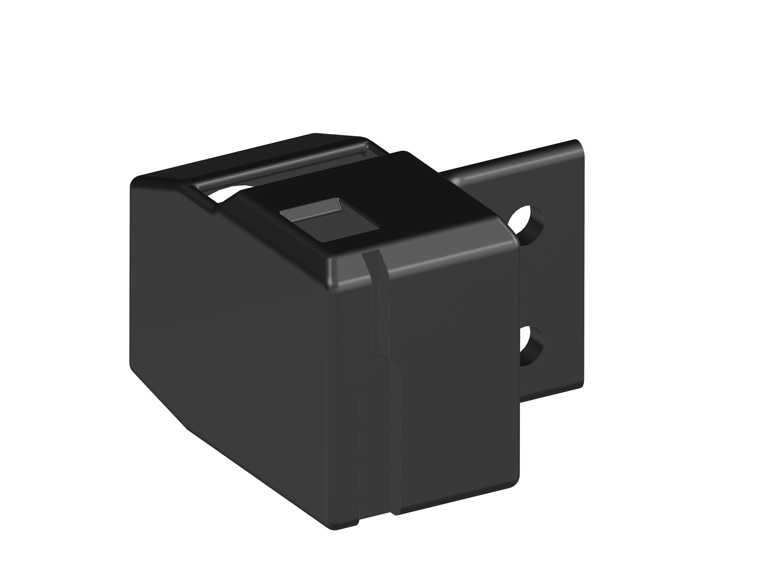
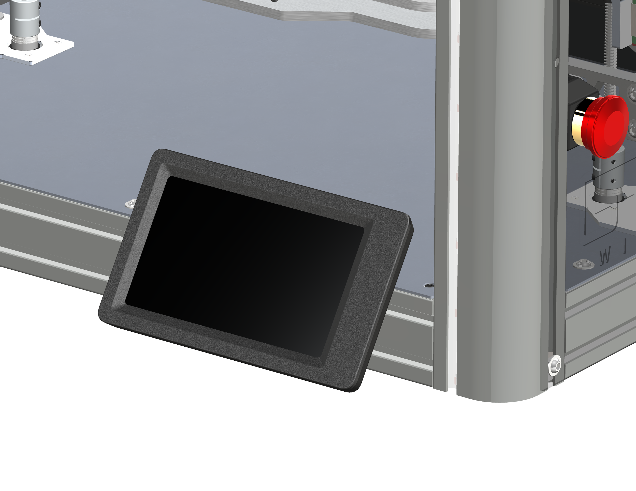
User Interface Mount
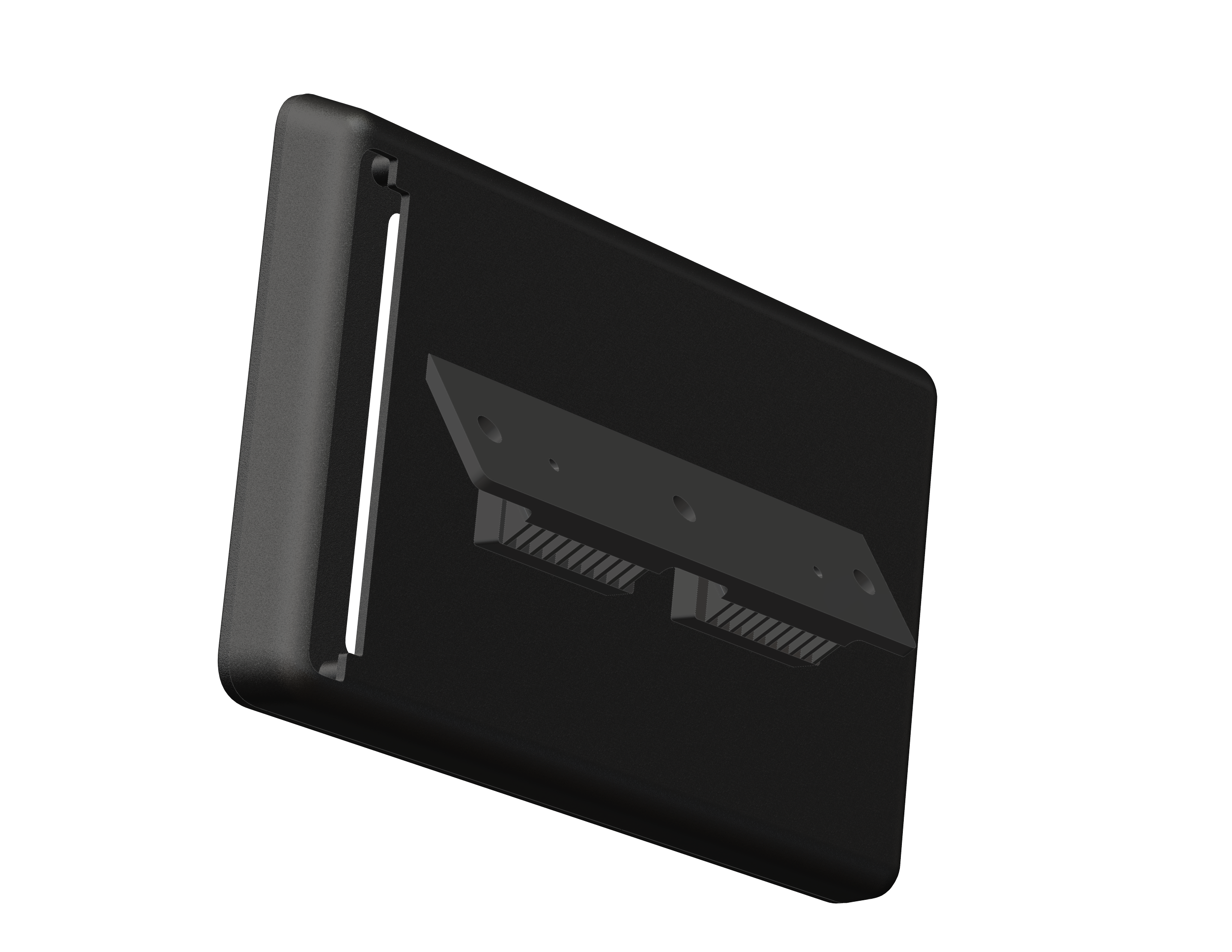
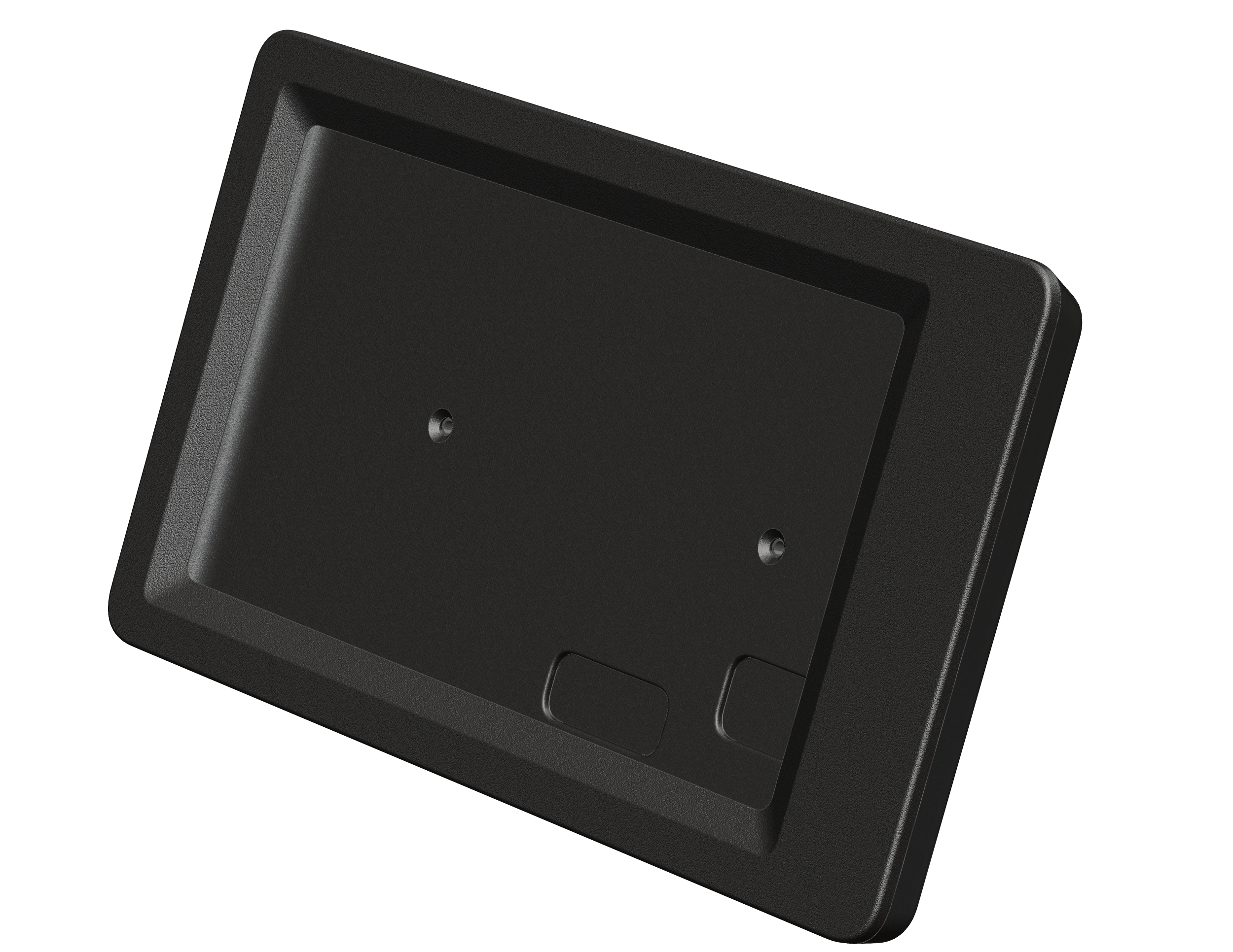
The front-facing user interface is where the user will be directly interacting with the machine, and therefore needs to not be distracting and bulky. The mount also needed to provide the most low-profile route for the wires coming from the screen.
This part went through three major redesigns over the course of the design phase. It began as a bulky mount that would slide into the aluminum extrusions with 3D printed features as part of the mount, and ended up as this more professional-grade design that utilized holes in the back to bolt into the aluminum extrusions.
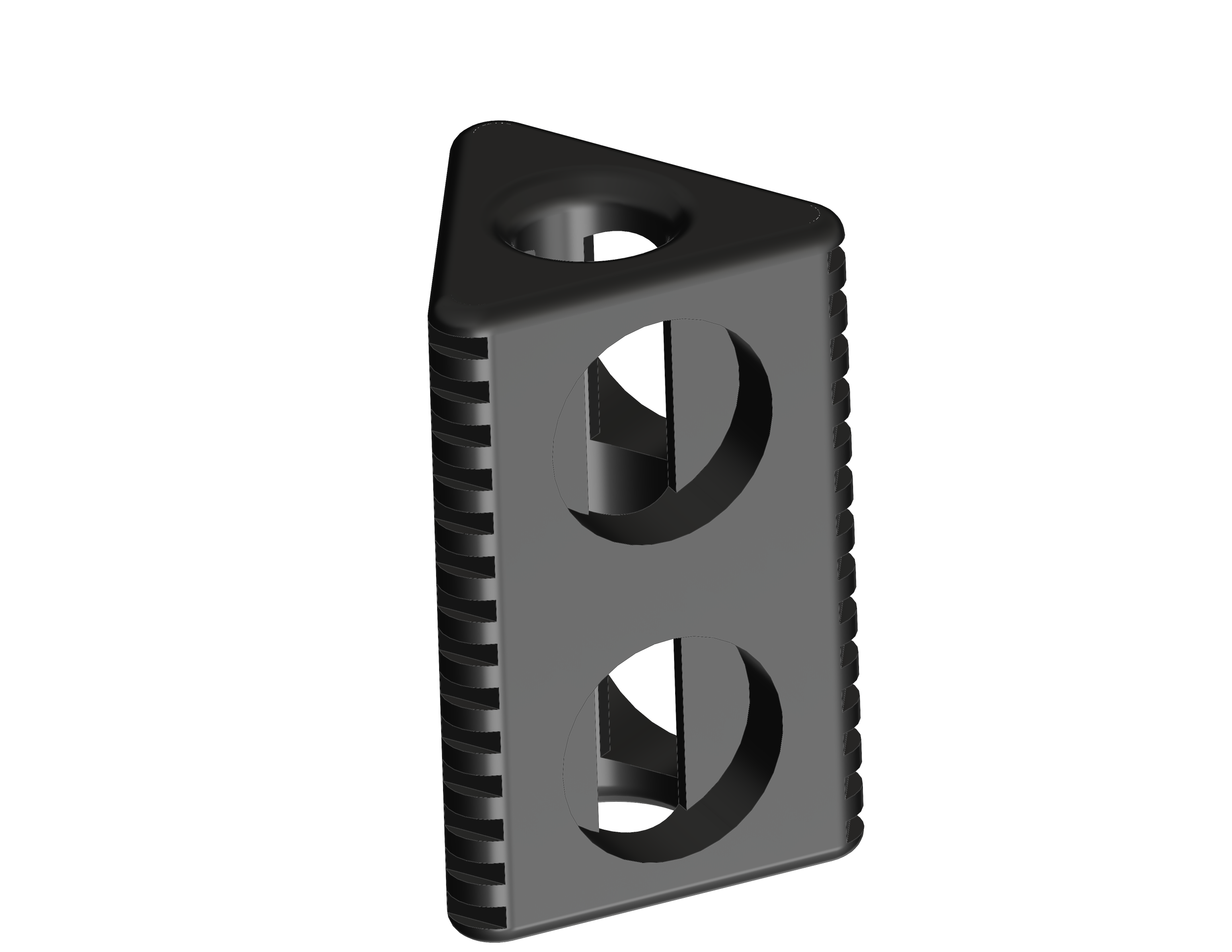
Magnetic Tube Loader
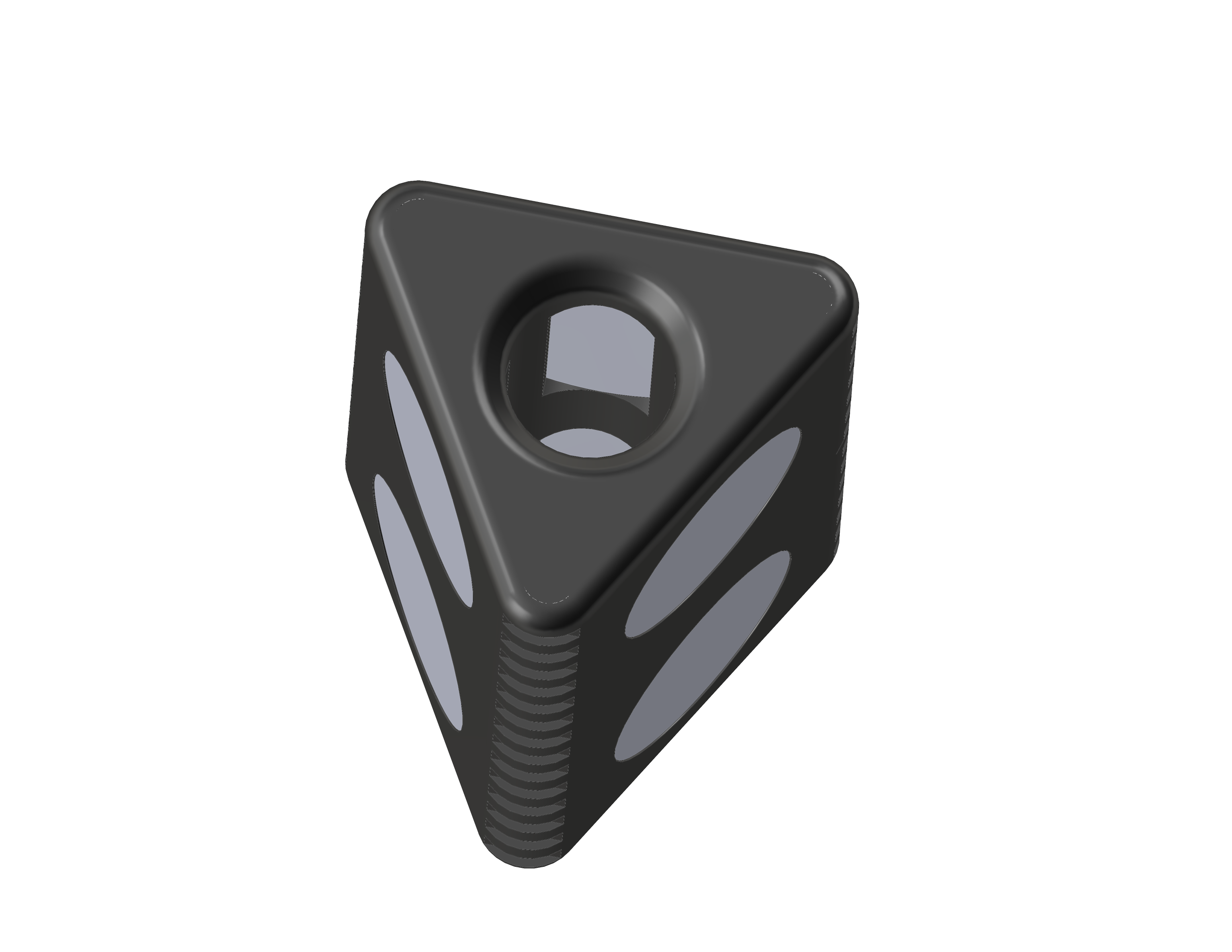
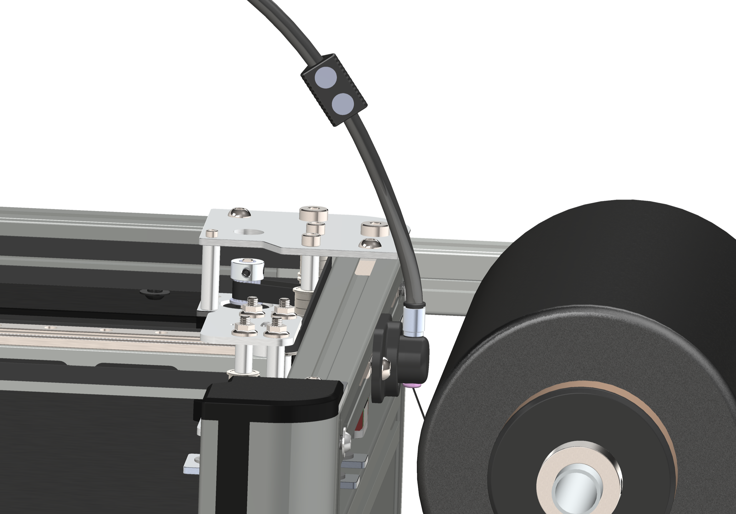
During the assembly and initial testing phase, it was discovered that manually loading the carbon fiber through the Teflon tube all the way to the toolhead was difficult and wasted a lot of time. No simple solutions were found as the fiber is very limp, meaning it cannot simply be pushed through like 3D printer filament. We determined that attaching a magnetic pin to the end of the fiber and leading it through the tube with a magnet would be an elegant solution.
This part went through two major redesigns. It was originally designed for much smaller magnets, as preliminary calculations showed that smaller magnets would be strong enough, though in reality this turned out to not be the case due to unforeseen friction, and larger magnets were needed. A triangular shape was the most efficient shape for this part, as due to the size constraints of the magnets we needed and the size of the tube we could not do a rectangular part with magnets on all four sides. The second version of the part was rectangular but only had magnets on two sides, and had a weaker magnetic effect. Due to the magnets being so close together there was also some interference in the magnetic fields, though thankfully two of the members on the team had experience with magnets and instructed me to have an opposite orientation for each of the two ranks, leading to a harmonized magnetic field, which was a phenomenon that I was not previously aware of.

If you are interested in learning more about the GridWinder project, please contact me at evan.soontiens@gmail.com and I would be happy to provide a copy of our final design report.